|
start - tips - pictures - signal flow - presets - repair dead keys | apps: patch editor - sysx analyzer | midi: sysx structure - cc messages - BCF2000
How 49 keys communicate through 16 wires
This picture gives you also a very clear view on the working of the keyboard scanning matrix.
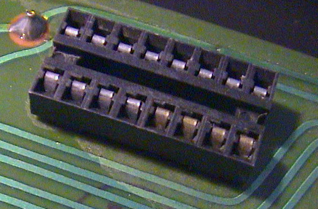
This is the socket. One row sends the current one by one to the metal pins ("the columns"), the other row receives the current in parallel when a key in the group is pressed ("the rows").
And this is the keyboard. The arrows show where each metal pin (=the columns) begins and ends, so where the metal wire is cut.
There are 8 keys (=the rows) for each metal pin, except for the first and the last (4 keys and 5 keys).
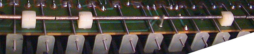
Each metal pin is soldered to the board halfway its running length and kept in place by 2 white plastic clams.
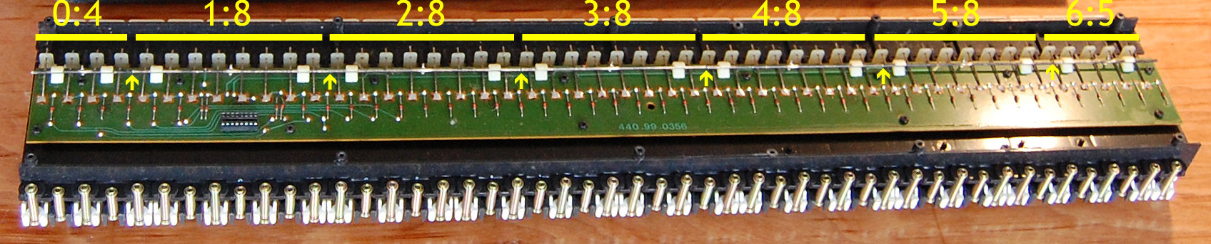
The processor puts current on the 7 long metal pins (0 to 6) one by one in a cycling way and thus detects which keys are pressed, by probing whether there is current on any of the contacts (=keys pressed) for that segment.
And you can also see clearly the 49 diodes keeping the current from flowing back to other keys and thus preventing misreads. Sweet.
Here you can see the metal "column" wires, the cuts and the soldered pin in the middle of the wire more clearly.